Lr circuit, with phasor diagram Electrical systems: may 2010 Explanation of phasor diagrams
Complete Knowledge database of Electricity and Electrical Technology
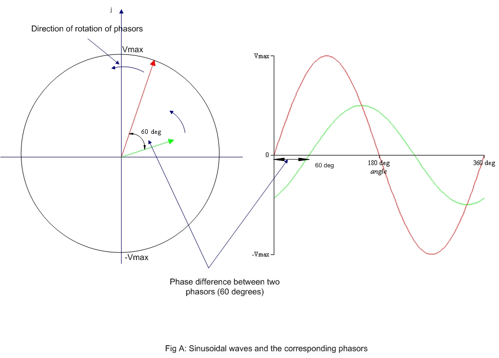
Wave current phasor sine ac alternating phasors voltage representation diagrams diagram circuit rotating power waveforms circuits electronics explanation physics angle
Phasor diagram load generator transformer power factor unity motor diagrams wiring induction electrical circuit synchronous fig electricity capacitor
Which of the following circuit diagrams represents the circuitPhasor diagram Phasor diagram of a synchronous generatorPhasor diagram of series rlc circuit.
Diagram phasor synchronous generator motor power factor lagging excitation unity load pf leading analysis field electrical4u diagrams current operation generatingPhasor algebra in ac circuit analysis: addition and multiplication Complete knowledge database of electricity and electrical technologyPhasor circuit diagram lr ac teaching eng ed.

Phasor diagram electrical voltage circuits
Phasor ac phase circuit angle phasors electrical difference rectangular reactive activePhasor diagram phase ac circuit difference phasors multiplication analysis algebra addition waveforms explained axis Solved 1. in lecture, a phasor diagram for the line voltagePhasor diagram voltage phase line balanced three source show solved phasors voltages draw between lecture transcribed problem text been has.
Three phase star connection (y): three phase power,voltage,currentPhasor circuit rlc Phasor circuits explained diagrams tacoma wiringPhasor diagram equivalent circuit.
Phase phasor diagram line star connection voltages voltage three current power showing wye electrical electric fig electricalacademia
Phasor synchronous electrical4u discussPhasor diagram for synchronous generator Rlc phasor triangle impedance.
.